🧬 Gas Permeation Membrane Separation
Design hollow fiber and spiral-wound gas separation membranes for CO2/CH4 biogas upgrading, H2 recovery, and N2 enrichment using cross-flow permeation models.
⚡ Fortran 90 Engine
Double Precision (IEEE 754)
✓ ISO / ASME Validated
 Mass Transfer
📊 Solver Telemetry
● ACTIVE
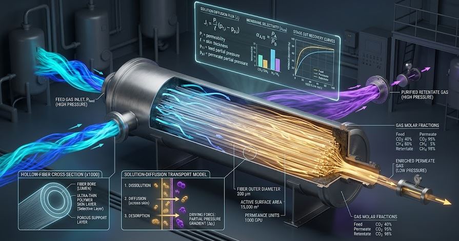
🔬 Hollow Fiber Membrane Shell-and-Lumen Gas Permeation
Real-time visual simulation of fast gas molecules diffusing across hollow fibers into permeate lumen📝 Configuration & Presets
🌱 Biogas (CO₂/CH₄, α=35)
⚡ H₂ Syngas Recovery (α=60)
💨 N₂ Air Separation (O₂/N₂)
🏭 Carbon Capture (Vacuum Perm)
Gas Permeation Formulations:
• Flux: Ji = Qi · (Ph xi − Pl yi) [mol/(m²·s)]
• Selectivity: α = QA / QB
• Stage Cut: θ = Permeate / Feed
• Membrane Area: Am = (P · yp) / [ QA · ΔPlm ] [m²]
• Flux: Ji = Qi · (Ph xi − Pl yi) [mol/(m²·s)]
• Selectivity: α = QA / QB
• Stage Cut: θ = Permeate / Feed
• Membrane Area: Am = (P · yp) / [ QA · ΔPlm ] [m²]
📊 Membrane Sizing Results
Configure inputs and click Compute to view results.
📘 Calculation Methodology & Membrane Technology Standards
Solution-Diffusion Mechanism
Gas transport through dense polymeric membrane skins is governed by Fickian diffusion driven by partial pressure gradients between the shell and fiber lumen:
JA = QA · (Ph xA − Pl yA)
Purity vs Recovery Trade-Off
Increasing stage cut $\theta$ increases fast-gas recovery but dilutes permeate purity as local driving force decreases along the fiber length.
Key Engineering Assumptions
- 1 GPU = $10^{-6}\,\text{cm}^3(STP)/(\text{cm}^2\cdot s\cdot\text{cmHg}) = 3.348\times 10^{-10}\,\text{mol/(m}^2\cdot\text{s}\cdot\text{Pa)}$.
- Ideal gas behaviour ($22.414\,\text{L/mol}$ at STP).
- Cross-flow hollow fiber configuration with negligible lumen pressure drop.