
💻 Microchannel Heat Sink Sizer (MCHE)
Design microchannel heat sinks for high-power electronics (CPU/GPU/SiC): junction temperature Tj, total thermal resistance Rth (K/W), heat flux density (W/cm2), and pressure drop.
⚡ Fortran 90 Engine
Double Precision (IEEE 754)
✓ ISO / ASME Validated
 Heat Exchangers
📊 Solver Telemetry
● ACTIVE
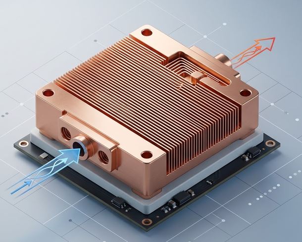
🔬 High-Density Microchannels & Thermal Heat Spreading
Real-time visual simulation: Micro-fin array with liquid coolant streams and heat conduction vectors📝 Configuration & Presets
🤖 700W AI Datacenter GPU
🖥️ 350W Server Direct-to-Silicon
🚗 1200W EV SiC Inverter
🧪 FC-72 Immersion Sink
Tuckerman & Pease Microchannel Formulation:
• Total Resistance: Rth = Rconv + Rcond + Rcaloric [K/W]
• Convective Resistance: Rconv = 1 / (h · Aeff) [K/W]
• Fin Efficiency: ηfin = tanh(m·Hc) / (m·Hc)
• Junction Temperature: Tj = Tin + Q · Rth [°C].
• Total Resistance: Rth = Rconv + Rcond + Rcaloric [K/W]
• Convective Resistance: Rconv = 1 / (h · Aeff) [K/W]
• Fin Efficiency: ηfin = tanh(m·Hc) / (m·Hc)
• Junction Temperature: Tj = Tin + Q · Rth [°C].
📊 Thermal Performance Results
📊 Output Summary
Chip Peak Junction Temperature (Tj)
44.9 °C
Thermal Resistance: 0.0284 K/W (C/W) | Heat Flux: 112.0 W/cm²
EXCELLENT (TJ < 70°C)
Convective Heat Coeff (h)
18167 W/(m²·K)
Microchannel convective slot
Microchannel Pressure Drop
34.1 kPa
0.34 bar pump head
Number of Microchannels
125 channels
120μm slot / 80μm fin
Temperature Rise (ΔTj-in)
19.9 °C
Inlet = 25 °C
📈 Junction Temp Tj (°C) vs Coolant Flow (mL/min)
📉 Total Thermal Resistance Rth (K/W) vs Channel Width (μm)
=================================================================
 THERMOFLUIDCALC — MICROCHANNEL HEAT SINK (MCHE) SIZING REPORT
=================================================================
Case Title                 : 700W AI Datacenter GPU Microchannel Cold Plate
Chip Heat & Dimensions     : Q = 700.0 W, Footprint = 25.0x25.0 mm (Heat Flux = 112.0 W/cm2)
Microchannel Array         : 125 channels (Wc = 120 um, Hc = 800 um, Ww = 80 um)
Coolant & Substrate        : Deionized Water (Optimal Thermal Performance) / Oxygen-Free Copper (k = 398 W/m·K)
Flow & Inlet Temperature   : V_flow = 1200.0 mL/min, Tin = 25.0 deg C
-----------------------------------------------------------------
CHIP JUNCTION TEMPERATURE  : 44.91 deg C (EXCELLENT (TJ < 70°C))
TOTAL THERMAL RESISTANCE   : 0.02844 K/W (deg C/W)
Convective Heat Coeff (h)  : 18166.9 W/(m2.K)
Microchannel Pressure Drop : 34.12 kPa (0.341 bar)
=================================================================
📘 Calculation Methodology & Electronics Cooling Standards
Tuckerman & Pease Microchannel Paradigm
By reducing hydraulic diameter down to tens of micrometers, the convective heat transfer coefficient $h \propto k/D_h$ reaches astronomical values (> 15,000 W/m²·K), enabling heat removal from ultra-dense processors exceeding $100\,\text{W/cm}^2$.
Three-Component Thermal Resistance Budget
The total junction-to-fluid thermal resistance includes $R_{cond}$ (substrate base conduction), $R_{conv}$ (fin convective resistance), and $R_{cal}$ (caloric fluid temperature rise along channel).
Key Engineering Assumptions
- Laminar flow with Kwak rectangular duct aspect-ratio corrections.
- 1D fin conduction efficiency across high aspect ratio micro-fins.
- Applicable to NVIDIA/AMD AI GPUs, Intel Xeon/AMD EPYC CPUs, and automotive EV SiC traction inverters.