
✈️ Turbine Blade Film Cooling Effectiveness
Evaluate gas turbine film cooling effectiveness (eta), adiabatic wall temperature (Taw), blowing ratio (M), momentum flux ratio (I), and protected wall heat flux reduction.
⚡ Fortran 90 Engine
Double Precision (IEEE 754)
✓ ISO / ASME Validated
 Convection
📊 Solver Telemetry
● ACTIVE
👁️ Views
44
⚡ Solves
37
💾 Downloads
490
📦 Fortran Code
10.8 KB
📅 Released
Jun 2026
⏱️ Latency
< 1 ms
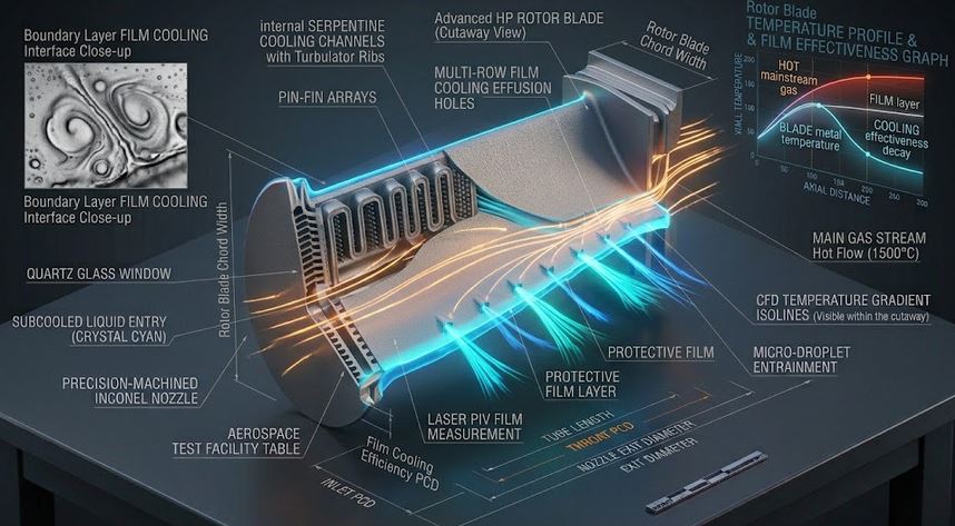
✈️ Turbine Airfoil Blade Wall & Protective Coolant Film Layer
Real-time visual simulation: Angled cooling hole injection discharging protective thermal barrier film📝 Configuration & Presets
🔥 HPT First-Stage Vane
🌀 Rotor Blade Showerhead
🏭 Combustor Effusion Tile
🚀 Scramjet Hypersonic Film
Goldstein & Baldauf Formulation:
• Blowing Ratio: M = (ρc Uc) / (ρ∞ U∞)
• Momentum Flux Ratio: I = (ρc Uc²) / (ρ∞ U∞²)
• Film Effectiveness: η = (Taw − T∞) / (Tc − T∞)
• Wall Heat Flux: q″ = h₀ · (Taw − Tw) [kW/m²]
• Blowing Ratio: M = (ρc Uc) / (ρ∞ U∞)
• Momentum Flux Ratio: I = (ρc Uc²) / (ρ∞ U∞²)
• Film Effectiveness: η = (Taw − T∞) / (Tc − T∞)
• Wall Heat Flux: q″ = h₀ · (Taw − Tw) [kW/m²]
📊 Film Cooling Results
📊 Output Summary
Film Effectiveness (η)
η = 0.132 (Centerline η₀ = 0.219)
Adiabatic Wall Temp: 1950.1 °C | Heat Flux Reduction: 19.2 %
ATTACHED FILM JET
Blowing Ratio (M)
1.22
Momentum ratio I = 0.41
Protected Wall Heat Flux
2,310.2 kW/m²
Uncooled = 2,860.0 kW/m²
Coolant Density Ratio (DR)
3.67
ρcoolant / ρgas
Normalized Distance (x/D)
24.0
Hole pitch P/D = 3.0
📈 Film Effectiveness η vs Downstream Distance x (mm)
📉 Protected Heat Flux q″ (kW/m²) vs Blowing Ratio M
=================================================================
 THERMOFLUIDCALC — TURBINE BLADE FILM COOLING REPORT
=================================================================
Case Title                 : Hypersonic Scramjet Combustor Strut Film Protection
Hole Geometry              : Diameter D = 2.50 mm, Pitch P = 7.50 mm (P/D = 3.0), Angle = 20.0 deg
Evaluation Location        : x = 60.0 mm (x/D = 24.0)
Mainstream Gas Flow        : Tinf = 2200.0 C, Uinf = 1200.0 m/s, rho = 0.60 kg/m3
Coolant Bleed Flow         : Tc = 300.0 C, Uc = 400.0 m/s, rho = 2.20 kg/m3 (DR = 3.67)
-----------------------------------------------------------------
BLOWING RATIO (M)          : 1.222
MOMENTUM RATIO (I)         : 0.407 [Attached Film]
FILM EFFECTIVENESS (eta)   : 0.1315 (Centerline eta_0 = 0.2192)
ADIABATIC WALL TEMP (Taw)  : 1950.1 deg C
Protected Wall Heat Flux   : 2,310.19 kW/m2
Uncooled Wall Heat Flux    : 2,860.00 kW/m2
Heat Flux Reduction        : 19.22 %
=================================================================
📘 Calculation Methodology & Film Cooling Standards
Goldstein & Baldauf Correlations
Computes the adiabatic wall temperature $T_{aw}$ resulting from the thermal mixing between the injected cold wall jet and mainstream boundary layer:
η = (Taw − T∞) / (Tc − T∞) = f(x/(MD), I, P/D)
Jet Attachment vs Lift-Off
When momentum flux ratio $I > 0.8$, the coolant jet lifts off the surface, entraining hot gas beneath before reattaching, degrading near-hole protection.
Key Engineering Assumptions
- Rows of discrete circular holes inclined at $\alpha \approx 30^\circ - 35^\circ$.
- Turbulent boundary layer mixing over flat or mildly curved airfoil walls.
- Applicable to gas turbine vanes, blades, combustors, and scramjet injectors.