
✈️ Airfoil Vortex Panel & Induced Drag
Compute NACA 4-digit airfoil lift coefficient (CL), induced drag (CDi), parasitic drag (CD0), lift-to-drag ratio (L/D), and pitching moment using lumped vortex panel theory.
⚡ Fortran 90 Engine
Double Precision (IEEE 754)
✓ ISO / ASME Validated
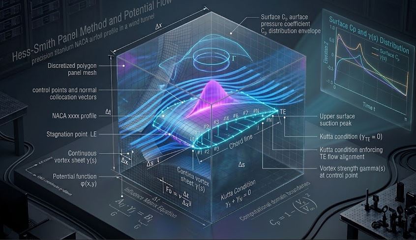 Cfd
Cfd
📊 Solver Telemetry
● ACTIVE
✈️ Cambered NACA Airfoil & Bound Vortex Circulation Field
Real-time visual simulation of angle of attack pitch, suction surface acceleration & trailing edge Kutta condition📝 Configuration & Presets
🛩️ NACA 2412 (General Aviation)
🚁 NACA 0012 (Symmetric)
🛬 NACA 4415 (High-Lift STOL)
🦅 Sailplane (AR = 22)
Lifting-Line Formulations:
• 3D Lift Slope: CLα = a₀ / [ 1 + a₀ / (π AR) ]
• Lift Coeff: CL = CLα (α − α₀L)
• Induced Drag: CDi = CL² / (π e AR)
• Total Drag: CD = CD0 + CDi | L/D = CL / CD
• 3D Lift Slope: CLα = a₀ / [ 1 + a₀ / (π AR) ]
• Lift Coeff: CL = CLα (α − α₀L)
• Induced Drag: CDi = CL² / (π e AR)
• Total Drag: CD = CD0 + CDi | L/D = CL / CD
📊 Airfoil Aerodynamic Results
📊 Output Summary
Aerodynamic Efficiency (L/D)
L / D = 23.2
Lift Coeff: CL = 0.584 | Total Drag: CD = 0.0252
α = 4.0°
Induced Drag (CDi)
0.0171
67.7 % of total drag
Parasitic Profile Drag (CD0)
0.0081
Skin friction + form
Zero-Lift Angle of Attack (α0L)
-2.30°
Camber effect
Quarter-Chord Moment (CM,c/4)
-0.0188
Pitching moment
📈 Lift Coefficient C_L vs Angle of Attack α (deg)
📉 Drag Polar: Lift C_L vs Total Drag C_D
=================================================================
 THERMOFLUIDCALC — AIRFOIL VORTEX PANEL AERODYNAMICS REPORT
=================================================================
Case Title                 : NACA 2412 General Aviation Light Aircraft Wing
Wing Planform              : Chord = 1500 mm, Aspect Ratio AR = 7.5, Oswald e = 0.85
NACA Profile Definition    : NACA 2412 (m = 2.0%, p = 0.4, t = 12%)
Operating Angle of Attack  : 4.00 degrees (Zero-lift alpha0 = -2.30 deg)
-----------------------------------------------------------------
LIFT COEFFICIENT (CL)      : 0.5845
TOTAL DRAG COEFF (CD)      : 0.02520
Parasitic Skin Drag (CD0)  : 0.00814
Induced Vortex Drag (CDi)  : 0.01706 (67.7% of CD)
LIFT-TO-DRAG RATIO (L/D)   : 23.20
Pitching Moment (CM_c/4)   : -0.0188
3D Lift Slope (dCL/dalpha) : 0.0928 per degree
=================================================================
📘 Calculation Methodology & Airfoil Theory Standards
Lumped Vortex & Lifting-Line Theory
Thin airfoil theory replaces the mean camber line with a distributed bound vortex sheet satisfying the Kutta condition at the sharp trailing edge:
CL = 2π (1 + 0.77 t/c) [ α − α0L ] / [ 1 + 2/AR ]
Induced Drag & Aspect Ratio
Tip vortices generated by finite span create downwash $w$, tilting the lift vector backward and producing vortex-induced drag $C_{Di} = C_L^2 / (\pi e AR)$.
Key Engineering Assumptions
- Incompressible subcritical flow ($Mach < 0.3$).
- Pre-stall linear attached flow regime ($\alpha < 14^\circ$).
- Standard NACA 4-digit analytical thickness and camber distributions.