
✈️ Lift & Airfoil Calculator
Analyze NACA 4-digit airfoils using thin airfoil theory with finite-wing corrections. Outputs CL, CD, CM, polar diagram, and airfoil shape.
⚡ Fortran 90 Engine
Double Precision (IEEE 754)
✓ ISO / ASME Validated
 Fluid Mechanics
📊 Solver Telemetry
● ACTIVE
👁️ Views
123
⚡ Solves
97
💾 Downloads
549
📦 Fortran Code
4.5 KB
📅 Released
Jun 2026
⏱️ Latency
< 1 ms
🪽 Airfoil Shape
📝 Configuration
Key Equations:
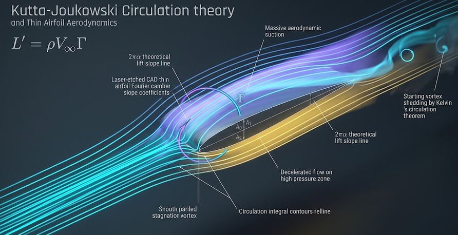
Thin airfoil: CL = 2π(α − αL0)
Finite wing: CL3D = CL2D / (1 + 2π/(π AR))
Induced drag: CDi = CL²/(πeAR)
NACA 4-digit camber and thickness distributions.
Thin airfoil: CL = 2π(α − αL0)
Finite wing: CL3D = CL2D / (1 + 2π/(π AR))
Induced drag: CDi = CL²/(πeAR)
NACA 4-digit camber and thickness distributions.
📊 Results & Polar Diagrams
Configure inputs and click Analyze to view results.
📘 Calculation Methodology
Mathematical Model
Thin airfoil theory provides CL = 2π(α−αL0) for 2D. Finite-wing corrections use lifting-line theory. Induced drag follows from the Oswald span efficiency factor. Post-stall CL reduction uses a simplified Viterna-like model.
NACA 4-Digit Series
The first digit is max camber (% chord), the second is position of max camber (tenths of chord), and the last two digits give max thickness (% chord). The thickness and camber distributions define the airfoil shape.
Assumptions
- Inviscid thin airfoil theory + viscous drag estimate.
- Parasitic drag from turbulent flat plate correlation with form factor.
- Simplified post-stall behavior.
- No compressibility correction (low Mach).
- Rectangular planform assumed for AR.