
♨️ Steam Trap & Flash Recovery
Size steam trap discharge capacities (with safety factors), calculate flash steam percentage, condensate return pipe diameter, and energy savings.
⚡ Fortran 90 Engine
Double Precision (IEEE 754)
✓ ISO / ASME Validated
 Thermodynamics
📊 Solver Telemetry
● ACTIVE
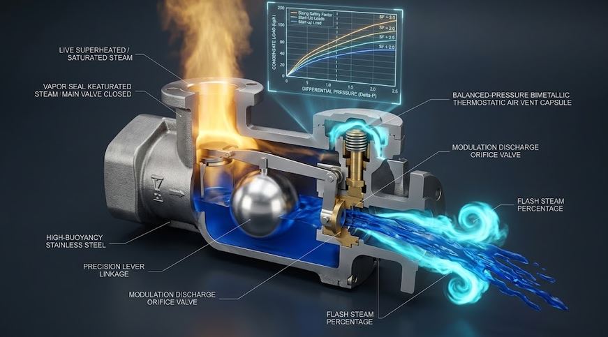
♨️ Steam Trap Condensate Drainage & Flash Vessel Phase Separation
Real-time visual simulation of flash steam re-evaporation & energy recovery📝 Configuration & Presets
💧 Steam Main Drip Leg (20 bar)
♨️ Process Reboiler (5000 kg/h)
🏥 Autoclave Fast Warmup
🏢 HVAC Heating Battery
Key Thermodynamic Formulations:
• Flash Steam %: xflash = (hf1 − hf2) / hfg2 · 100%
• Flash Flow: ṁflash = ṁc · xflash
• Design Trap Capacity: Qrated = ṁc · SF
• Return Line ID: D = √[4 Qflash / (π · Vallow)]
• Flash Steam %: xflash = (hf1 − hf2) / hfg2 · 100%
• Flash Flow: ṁflash = ṁc · xflash
• Design Trap Capacity: Qrated = ṁc · SF
• Return Line ID: D = √[4 Qflash / (π · Vallow)]
📊 Trap & Flash Recovery Results
Configure inputs and click Compute to view results.
📘 Calculation Methodology & Engineering Theory
Thermodynamics of Flash Steam
When high-pressure condensate discharges to a lower pressure region, the excess sensible heat causes spontaneous boiling into flash steam:
xflash = (hf1 − hf2) / hfg2 · 100%
Steam Trap Safety Factor Selection
Safety factors ensure rapid removal of initial cold startup condensate loads without waterlogging the heat exchanger matrix.
Key Engineering Assumptions
- Saturated condensate at trap inlet pressure $P_1$.
- Equilibrium flash vessel vapor separation without carryover.
- Two-phase velocity restricted below 15 m/s to prevent water hammer and line erosion.